
[音響撚]音響HIFI討論區(25)
qualcomm
1001 回覆
5 Like
7 Dislike
我想問一下
我是玩無源前級的
前級係一個繼電器音量控制 (電源只係用來切換電阻,唔會放大任何訊號)
入面冇任何牛
R2R DAC > R2R Passive Preamp > Power Amp
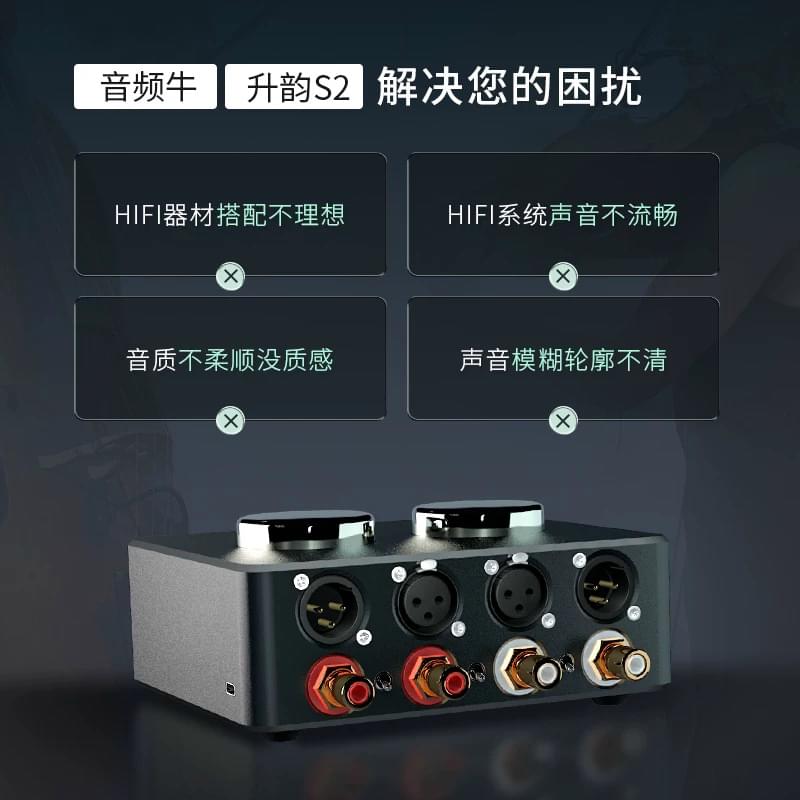
我覺得聲係很好通透
但比較平面,唔夠順滑,有毛刺感
高頻有啲炒耳
如果我喺前後加呢隻牛,有冇用?
R2R DAC > Transformer > R2R Passive Preamp > Transformer > Power Amp
我是玩無源前級的
前級係一個繼電器音量控制 (電源只係用來切換電阻,唔會放大任何訊號)
入面冇任何牛
R2R DAC > R2R Passive Preamp > Power Amp
我覺得聲係很好通透
但比較平面,唔夠順滑,有毛刺感
高頻有啲炒耳
如果我喺前後加呢隻牛,有冇用?
R2R DAC > Transformer > R2R Passive Preamp > Transformer > Power Amp
我全段係用 XLR
但佢呢隻都有
但佢呢隻都有
我問 ChatGPT
佢話前後都加牛,啲聲會牛 D
“From an electronics and signal‐integrity perspective, each transformer placement option affects the circuit’s isolation, impedance matching, and loading in different ways. Let’s analyze the four configurations:
1. Transformer Before the Attenuator:
In this setup, the source directly drives the transformer’s primary. The transformer buffers and transforms the source impedance, providing a stable, low‐impedance drive to the attenuator. This means that the attenuation network sees a well‐matched, “clean” signal regardless of variations in the source. However, the attenuator’s output is unbuffered, so any impedance variations there depend on the network itself and on the load (the amplifier input).
2. Transformer After the Attenuator:
Here the attenuator is connected directly to the source. The transformer placed afterward buffers the attenuator’s output before feeding it to the amplifier. While this configuration helps drive the amplifier (especially if it has a low input impedance), it leaves the attenuation network itself exposed to the source’s impedance variations. In other words, the source’s nonidealities can affect the attenuator’s performance because there is no input buffering.
3. Transformer Both Before and After the Attenuator:
This two‐stage buffering approach uses one transformer to isolate and match the source (before the attenuator) and a second transformer to buffer the attenuator’s output to the amplifier. In theory, this configuration provides the best overall impedance matching and isolation on both ends. The attenuator then operates with a well‐defined, buffered input and its output is likewise stabilized, minimizing variations and nonlinear loading effects. The main potential drawbacks are the increased component count, additional insertion loss, and possible phase or frequency response alterations introduced by the extra transformer stage. If high‑quality transformers (or autoformers) are used to minimize these drawbacks, the benefits can outweigh the disadvantages.
4. No Transformer (Resistive Attenuator Only):
A design without any transformer relies solely on a resistor (or stepped attenuator) network. While this is the simplest and most “transparent” in theory (since there is no magnetic component to introduce distortion or phase shift), it lacks any isolation or impedance transformation. Consequently, the attenuator must handle the full loading of both the source and the amplifier. This can result in variable attenuation, mismatched impedances, and potential signal degradation—especially if the source has a high output impedance or the amplifier a low input impedance.“
Scientific Comparison and Conclusion:
• Isolation and Impedance Matching:
Transformers (or autoformers) act as buffers and impedance transformers. Placing a transformer before the attenuator ensures the attenuator sees a low‐impedance, well‐matched drive. Similarly, placing one after the attenuator isolates its output from the amplifier’s load. Using both stages (configuration 3) therefore provides the maximum benefit in terms of isolation and impedance consistency.
• Signal Integrity and Nonlinearity:
A buffered (transformer–isolated) attenuator tends to operate more linearly and with reduced sensitivity to source or load variations. In contrast, a resistive network without any transformer (configuration 4) is more prone to nonlinear loading effects, which can alter the signal level and frequency response as the attenuation setting changes.
• Component Complexity and Loss:
While adding transformer stages (configuration 3) introduces additional complexity and potential insertion loss, high‑quality designs can minimize these issues. In practice, the slight additional loss is often an acceptable trade‑off for the improved isolation and matching.
Optimal Choice:
From a purely scientific and engineering standpoint, configuration 3 (transformer/autoformer both before and after the attenuator) is optimal if the goal is to maximize isolation and ensure that both the attenuator’s input and output see a constant, low, and well‑matched impedance. This configuration minimizes loading variations on the attenuator and provides a stable drive to the amplifier, yielding the highest potential fidelity. However, the extra transformer stage must be implemented with care to minimize insertion loss and preserve a flat frequency response. In systems where cost or simplicity is a higher priority and the source or amplifier already has a high impedance, a single transformer stage (either before or after, with a slight preference for the input side) may be acceptable—but these configurations do not fully solve both the input and output matching problems.
Thus, in a high‑performance differential passive design, the dual-transformer (or autoformer) approach (configuration 3) offers the best theoretical performance when executed with high‑quality components.
坐係正常聆聽位都覺大聲,定貼隻耳埋喇叭先聽到?
前者就唔太正常
前者就唔太正常

巴打你可以去潘氏膽藝試下隻PT2
我自己用緊PT1, 效果非常明顯
[耳機撚]召集大耳牛、枱式耳機系統用家(94)
- 分享自 LIHKG 討論區
https://lih.kg/ChuHrjX
Chat GPT講嘅野係同聽感關聯唔到,佢只係解釋咗用隻牛去隔DC,保護到後面部機。
大陸野我唔識,潘生隻牛係自己設計嘅
我自己用緊PT1, 效果非常明顯
[耳機撚]召集大耳牛、枱式耳機系統用家(94)
- 分享自 LIHKG 討論區
https://lih.kg/ChuHrjX
Chat GPT講嘅野係同聽感關聯唔到,佢只係解釋咗用隻牛去隔DC,保護到後面部機。
大陸野我唔識,潘生隻牛係自己設計嘅
似係個VR 問題?


隻牛終於到咗


直接結論講起
牛前牛後,無源繼電器步進式音量係中間
阻抗匹配更好
自然、通透、有動態、三頻平均
人聲有人性,樂器演繹更有感情
Testing Track:
中島美嘉 - 曾經我也想過一了百了 (first take version)
人聲清楚溫暖之餘,鋼琴聲清脆,最重要係支低音提琴有質感,做到個底出嚟
Cigarette after sex - Sweet
試低音氛圍
Cigarettes After Sex 既歌
只要低音一出唔到,做唔到個氛圍,係搞唔店
一出聲就知咩事
低音係完全無 Roll Off,個質感仲增強咗
但人聲竟然仲係清晰通透
Per se - 孤獨之塔
一樣,試男主音把聲
唔靚既系統,把聲會虛、沉、矇
結果係表現非常好!
清楚、演繹到有文青味嘅男聲
平野綾 - God Knows
試樂器分離度,清晰度
由於首歌樂器 arrangement 係比較複雜,加上強烈嘅女聲
電結他嘅演繹亦非常有技巧性
每樣嘢都非常清楚,有分離度
Kanon D Dur (Quartet) - Evangelion: Death OST
試定位,音場
四支提琴,定位準確,清楚分離
拉絃很好的質感
澤野弘之 - YouSeeBigGirl
試氣勢,爆發力
進擊的巨人非常大嘅壓迫感、臨場感
好似個幾十米嘅巨人企喺你面前一樣,身如其中
發揮得非常好
淘寶嘢嚟講
我覺得有點少貴,但係值得
耳朵高潮了
非常推介各位玩無源前級
補充:
女聲中撚晒毒
女聲中撚晒毒


我唔知潘生 pt2 係咩黎…